Windtunnel Design & Construction – part 7: diffuser
The diffuser morphs the airflow from the rectangular section to the round inlet of the fan.
This proved to be the most complex part to build. Though the contraction duct was larger and heavier, the wall sheets only had to be bent in one plane. This was easy and required little force.
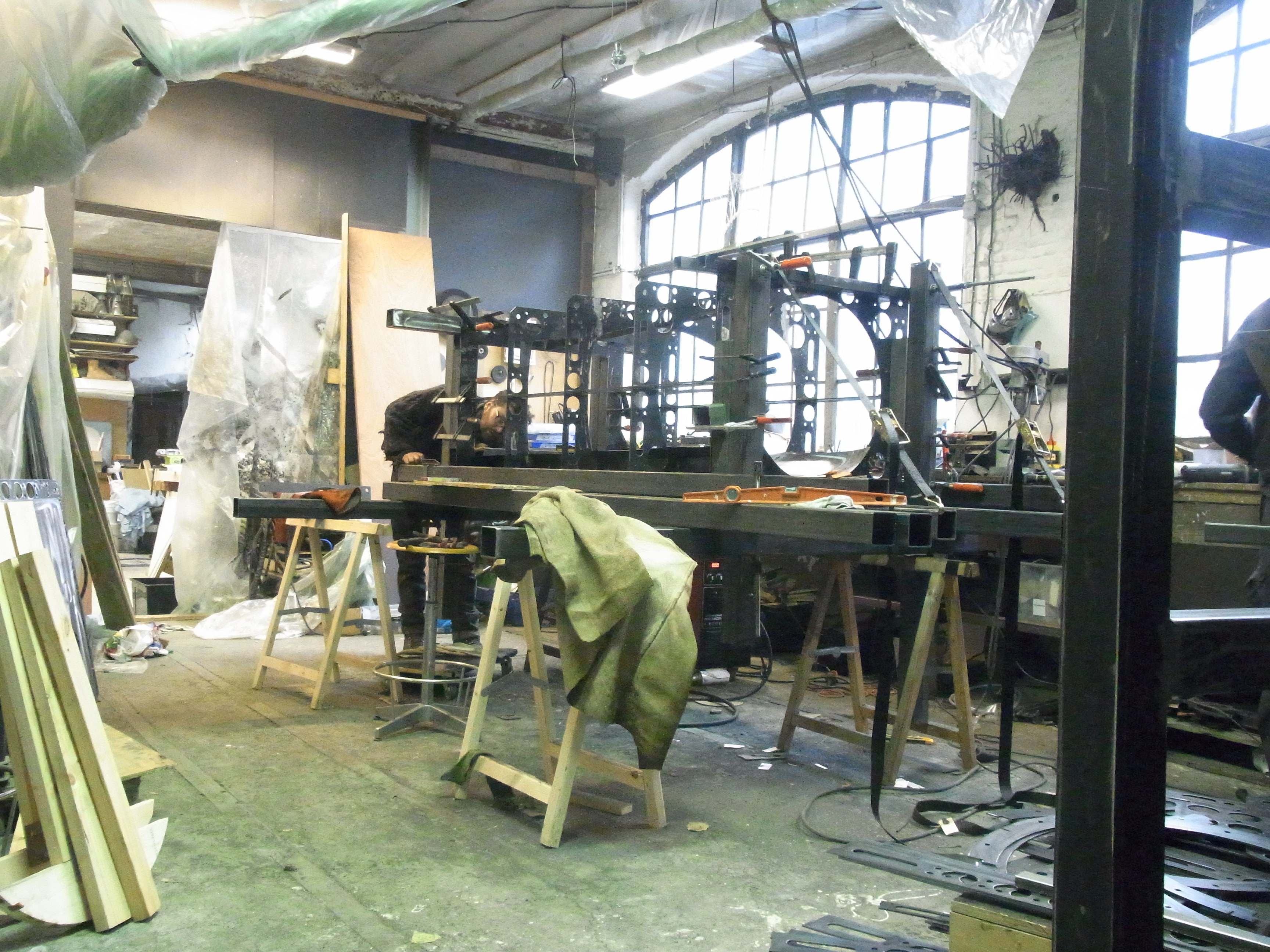
The diffuser wall is assembled from 4 cut-to-size sheets that need to bend in both directions.
The same method of conforming the inside wall sheets to the outer frame was used.
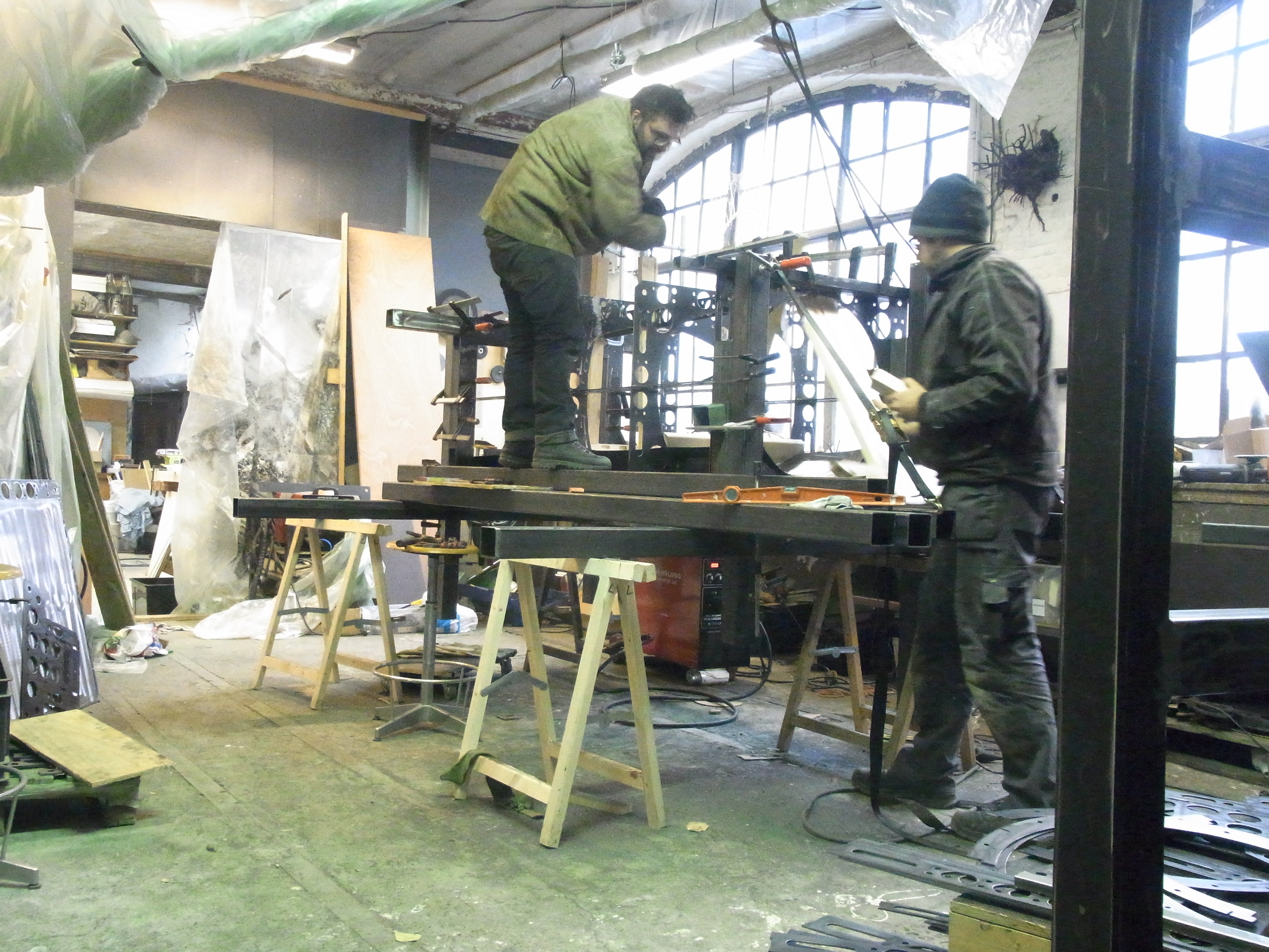
After clamping the structure to the assembly table, the cut-to-size wall sheets were made to conform using wooden blocks and hydraulic car jacks.
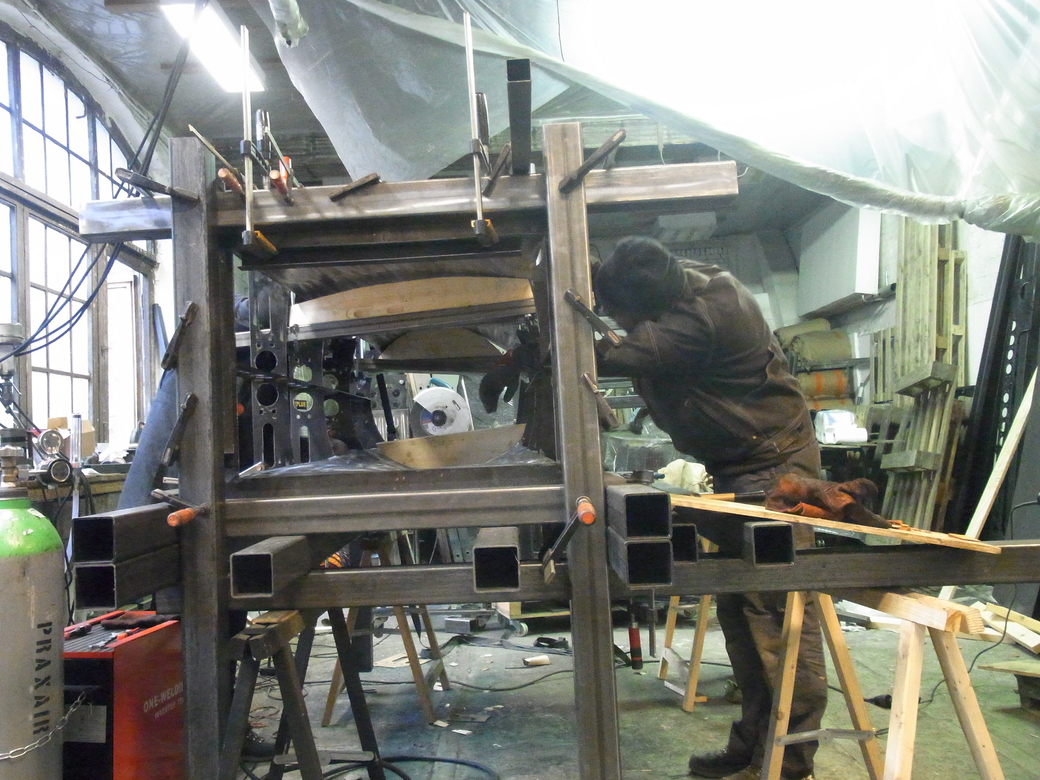
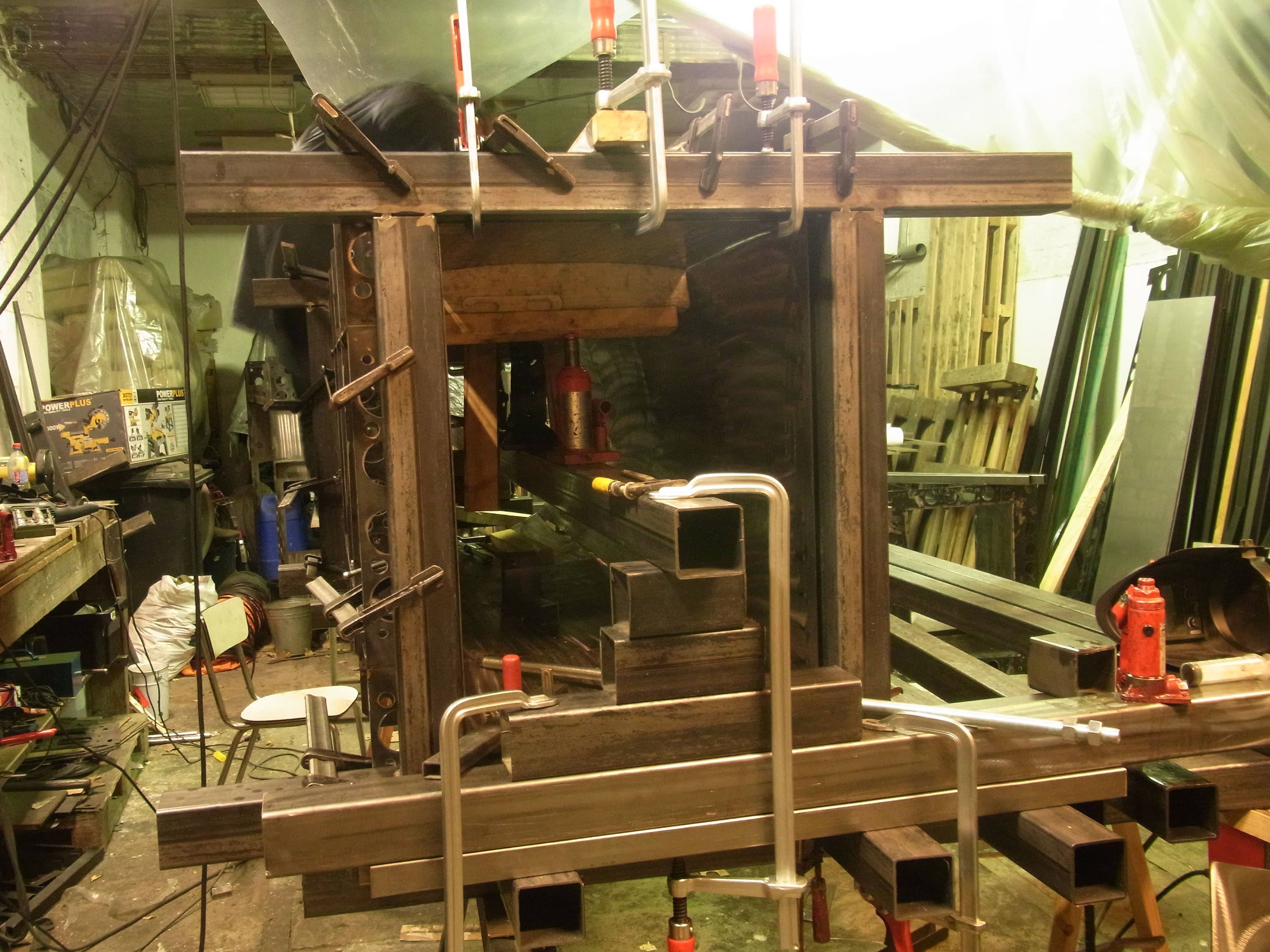
Each time one cross-section of the wall pieces lined up properly, it was tack-welded in place. We then proceeded to the next cross-section and repeated the process.
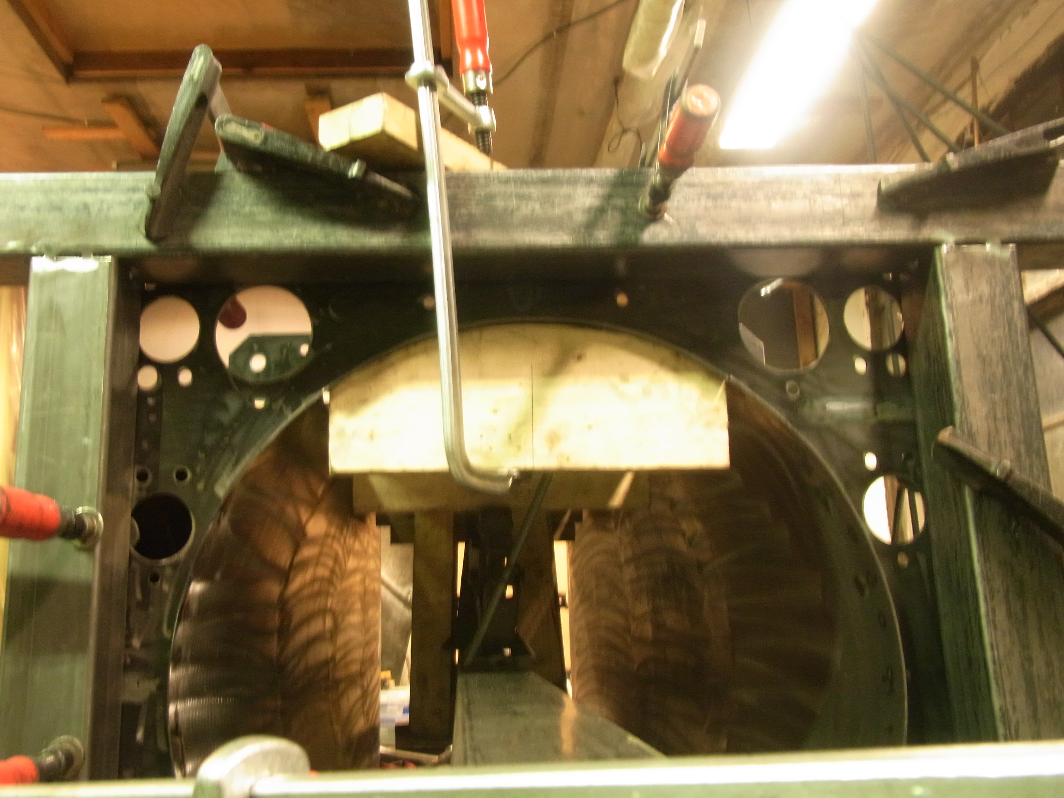
This was done for all 4 wall sheets. A beam was mounted through the center of the diffuser to provide a base for the jacks.
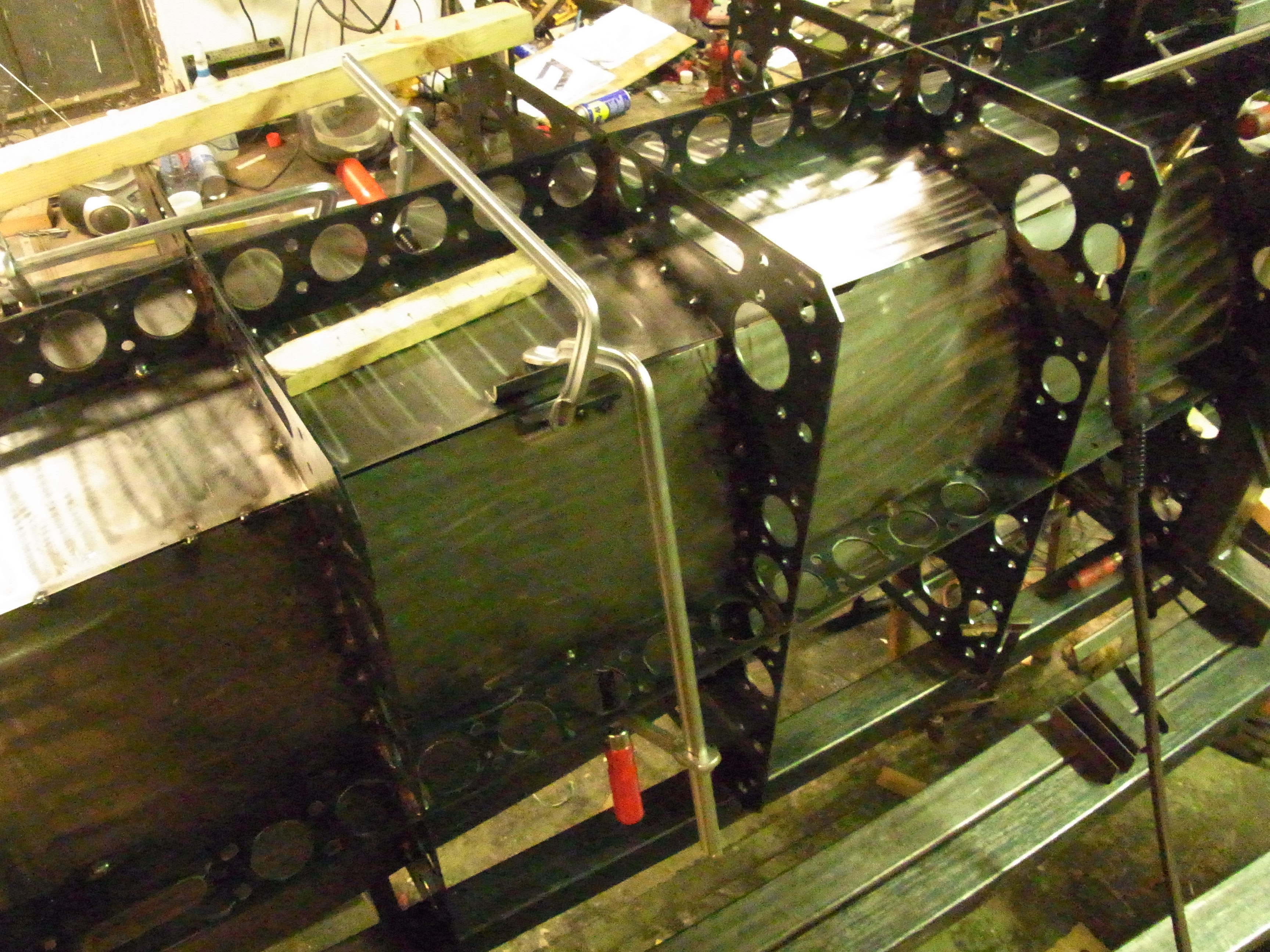
Forcing the plates to bend in both directions introduced so much stress that, afterwe got the wall plates to conform to the cross-sections, the edges of the 4 wall plates did not line up. They touch at the cross-sections, but bend outward between those sections.

This was corrected by tacking on handles, clamping the edges together using these handles and tack-welding the edges.
The final part looks great, but this is the piece where we had to hide the most mistakes. A polyester putty was used to smooth out dents caused by the bending process.
If we would do this again, I would try carving fold lines into the plates with the laser. We had considered this beforehand, but after the contraction duct had worked out so be so easy to put togethers, we had deemed it unnecessary.