
Windtunnel Design & Construction – part 2: design
For reasons of durability the design brief preferred a steel-walled wind tunnel.
The tunnel was conceived as a series of self-supporting parts, to be bolted together.
Each of the wind tunnel component parts was to be built from lasercut steel parts.
From right to left the wind tunnel consists of:
-a bellmouth (a rounded inlet)
-several casings, which form the settling chamber and allow for the mounting of screens and honeycomb inbetween the casings.
-a contraction duct, which accelerates the air from the low-speed inlet to the high-speed test section
-a test section with reconfigurable extension parts
-a diffuser that provides a smooth transition from the rectangular test section to the round inlet of the fan
-an 11kW fan
The entire tunnel is supported on a steel frame.
The parts from the bellmouth up to the contraction duct are mounted on a rail system. This provides easy access to the screens
The test section is mounted on castor wheels to allow for the exchange of test sections (two interchangeable test sections are to be built)
Overall dimensions are:
-windtunnel length 10.3m
-inlet section 1750mm wide x 1250 mm high
-test section 700mm wide x 1250 mm high
-fan diameter 630mm
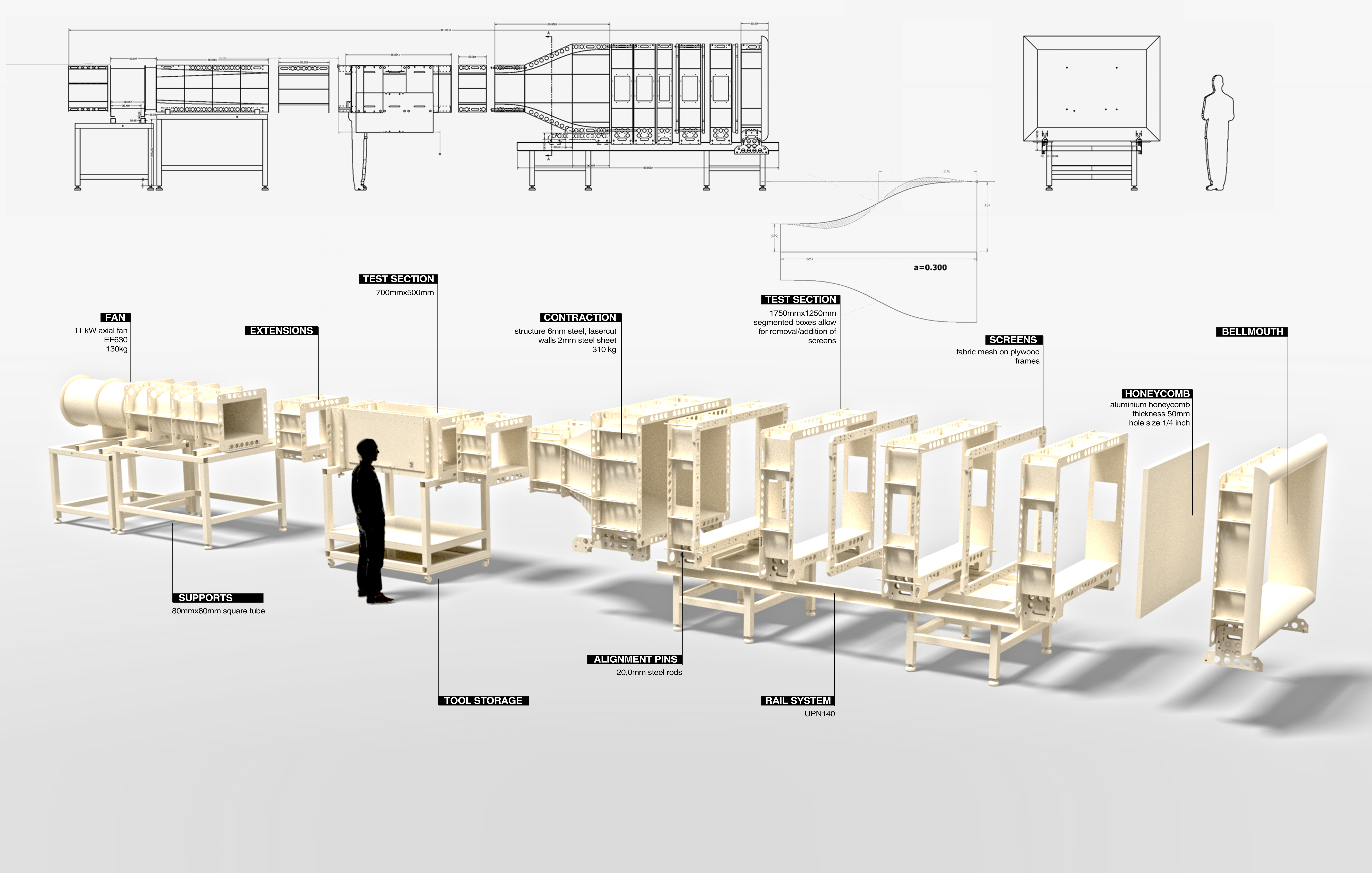
The wind tunnel parts are made from 2mm steel walls, inside a frame made from 6mm thick lasercut pieces.
The tunnel design was modeled in Autodesk Inventor. As the requested delivery date was relatively short, it was decided to start construction in parallel with developing the 3D-model.
At the time the above rendering was made, the settling chamber boxes and the contraction duct had already been made.
For dimensions and general design rules the following papers were useful:
-James H. Bell and Rabindra D. Mehta, CONTRACTION DESIGN FOR SMALL LOW-SPEED WIND TUNNELS, Stanford University, April 1988
R.D.Mehta and P. Bradshaw, Design rules for low speed wind tunnels, Aero. Journal (Royal Aeronautical Society), Vol. 73, p. 443 (1979).